Results 1 to 23 of 23
  1. #1
    Senior Member rodorico83's Avatar
    Join Date
    07.17.13
    Location
    Madrid, Spain
    Posts
    149
    Liked: 8

    Default about breather tanks overflow

    Hi guys.
    i have some issues with the breather tank in my f3000.
    After full car rebuild, i tested on small track and notice that my breather tank was overflowing as the catch tank was full in term of some minutes. so i replaced with slighly bigger one and removed some oil from dry sump and testing at home i can still see that the breather tank is filling quickly with aprox 5000 rpm or above for some seconds and oil stays at same level when i release and i leave it at idle. the tank is connected with the top of the drysump and also has a breather hose.
    im concern that i can not take out more oil as the level is almost at bottom (aprox 4cm above) when not running, however i tried to measure the level at ldle condition but no way to see it with a camera
    if the sump is overflowing and filling the breather tank which is higher of breather hose why i can not see oil on breather hose.
    When at idle breather tank does not empty ??
    breather tank is 1l, transparent hose is the breather one
    some pics of the setup and the amount of oil some minutes after stopping engine.

    Attached Thumbnails Attached Thumbnails Click image for larger version. 

Name:	1715283379473 (Small).jpg 
Views:	738 
Size:	57.9 KB 
ID:	111185   Click image for larger version. 

Name:	1715283379468 (Small).jpg 
Views:	755 
Size:	91.2 KB 
ID:	111186   Click image for larger version. 

Name:	1715283379460 (Small).jpg 
Views:	744 
Size:	91.1 KB 
ID:	111187  


  2. #2
    Contributing Member
    Join Date
    10.08.06
    Location
    San Jose, Ca
    Posts
    816
    Liked: 118

    Default

    So you have a dry sump tank, connected to a breather tank, connected to a overflow tank? Seems to me that you should only need two, the dry sump and a breather/overflow. If your second breather tank is filling up after a few minutes of running in the shop your dry sump tank is too small, or you have too much oil, or both.

  3. #3
    Senior Member rodorico83's Avatar
    Join Date
    07.17.13
    Location
    Madrid, Spain
    Posts
    149
    Liked: 8

    Default

    Quote Originally Posted by 10rmotor View Post
    So you have a dry sump tank, connected to a breather tank, connected to a overflow tank? Seems to me that you should only need two, the dry sump and a breather/overflow. If your second breather tank is filling up after a few minutes of running in the shop your dry sump tank is too small, or you have too much oil, or both.
    correct i have dry sump connected to breather tank by 2 hoses and then breather tank to plastic overflow tank , on first instance i found the overflow tank full in short period of time, so i changed both tanks for a 1liter size before was 0.5, and removed 0.7l of oil from dry sump.
    testing at home i see the breather tank filling up quickly when high rpm is applied for seconds and it does no restore when returning to idle.
    but i can not see any oil in the breather hose (transparent one) that connects dry sump and breather tank which is at lower height than breather tank itself so i dont understand this point ??
    dry sump size is ok is 6 1/2 litres, 13 cm below top
    lola manual states use catch tank > 3l but i guess in case of breather tank smaller can be used.

  4. #4
    Contributing Member
    Join Date
    10.08.06
    Location
    San Jose, Ca
    Posts
    816
    Liked: 118

    Default

    How big is the engine? 3L? At first glance 6L seems a bit small. How much oil are you running? Has this always been an issue or is this problem new?

  5. #5
    Senior Member rodorico83's Avatar
    Join Date
    07.17.13
    Location
    Madrid, Spain
    Posts
    149
    Liked: 8

    Default

    Quote Originally Posted by 10rmotor View Post
    How big is the engine? 3L? At first glance 6L seems a bit small. How much oil are you running? Has this always been an issue or is this problem new?
    is 3.5l, note that 6 1/2 is still 13 cm below top, good question i can not remember how much oil i put as has been long time but only took the car once to the track as i had no time, but i believe i should had put around 6l, is a new build car with this engine a gearbox, but i know others cars with same combination.

  6. #6
    Contributing Member Rick Kirchner's Avatar
    Join Date
    02.24.02
    Location
    Tehachapi, CA
    Posts
    6,679
    Liked: 1630

    Default

    does the breather system connect to the valve covers?

    If so, do you have oil restrictors in the head oiling system? Many race pumps will supply so much volume to the heads that it needs to be restricted.

    If the heads are getting a ton of oil, it may not have time to drain back into the crankcase when cold.

    If you have a lot of blowby and crankcase pressure then i could see that being a double whammy.

  7. The following members LIKED this post:


  8. #7
    Senior Member
    Join Date
    08.22.15
    Location
    Westfalia
    Posts
    1,924
    Liked: 1270

    Default

    Qualifying that I know nothing about your oiling system.

    But as Rick said, this sounds like it could be induced by excess blowby, and a leakdown test is where I’d start. Also, if the crankcase pressure isn’t venting properly, and/or you’re running too much oil, the next result could well be oil leaks from wherever is the path of least resistance.
    Once we think we’ve mastered something, it’s over
    https://ericwunrow.photoshelter.com/index

  9. #8
    Senior Member rodorico83's Avatar
    Join Date
    07.17.13
    Location
    Madrid, Spain
    Posts
    149
    Liked: 8

    Default

    Quote Originally Posted by Rick Kirchner View Post
    does the breather system connect to the valve covers?

    If so, do you have oil restrictors in the head oiling system? Many race pumps will supply so much volume to the heads that it needs to be restricted.

    If the heads are getting a ton of oil, it may not have time to drain back into the crankcase when cold.

    If you have a lot of blowby and crankcase pressure then i could see that being a double whammy.
    both heads are connected to breather tank indeed, i will check but i dont remember to notice high pressure on these lines.
    oil restrictors, i dont think so but i will double check with Solution F.
    blowby or cranck pressure i dont think so, i did leakdown test before installing engine, everything was fine, however i will cross check again.

    I more less manage to measure dry sump level on idle with weld tig rod inside hose from the top of dry sump, and oil was sitting about 21/23 cm above bottom, just above baffles , im happy with this level. maybe i just really need to put a bigger breather tank...

  10. #9
    Senior Member
    Join Date
    09.25.16
    Location
    Colorado
    Posts
    111
    Liked: 28

    Default Breather tank overflow

    Rodrigo
    Ive had a similar problem after an engine rebuild. Tried installing an oiling system restrictor but that didn’t help. Turned out to be a bad scavenge side of the oil pump. Check the clearances in your pump.

    best of luck
    Tom

  11. The following members LIKED this post:


  12. #10
    Senior Member rodorico83's Avatar
    Join Date
    07.17.13
    Location
    Madrid, Spain
    Posts
    149
    Liked: 8

    Default

    Quote Originally Posted by Bobsy SR 6 View Post
    Rodrigo
    Ive had a similar problem after an engine rebuild. Tried installing an oiling system restrictor but that didn’t help. Turned out to be a bad scavenge side of the oil pump. Check the clearances in your pump.

    best of luck
    Tom
    Hi Bobsy.
    What symptoms you had ??
    just rescue from my mails with solution F "There is 3 scavenge stages and one double pressure stage with valve pressure stage", oil pressure has been ok at cold, warm, idle ...
    pump has been rebuild by Solution F, is even bolt wired.

  13. #11
    Member jcolley's Avatar
    Join Date
    08.05.10
    Location
    Portland, Maine
    Posts
    85
    Liked: 25

    Default

    Quote Originally Posted by rodorico83 View Post
    Hi Bobsy.
    What symptoms you had ??
    just rescue from my mails with solution F "There is 3 scavenge stages and one double pressure stage with valve pressure stage", oil pressure has been ok at cold, warm, idle ...
    pump has been rebuild by Solution F, is even bolt wired.
    I had an Ultima GTR through the shop a couple of years ago with a really loosely built LS7. When it came in, the engine could would fill the oil sump breather catch can to overflow in less than 10 miles of driving.

    We went through a lot until we solved it.

    First off, since the scavenge pump will pull oil, air, small children...pretty much anything out of the oil pan, we blocked off the valve cover vents to reduce air coming in. Dyno showed a bit of gain pulling the crankcase to a light vacuum and this somewhat reduced the catch can oil filling. The owner was very concerned of over-vacuum on the crankcase so to ease his nerves, I installed a MAP sensor to monitor crankcase vacuum; side benefit is being able to monitor ring health in the long term.

    Finally, it occurred to me that since the engine had so much blowby being a very loose build, the single 8AN breather line from the sump tank to the catch can was seeing very high volumetric flow rate and entraining oil over to the catch can. My theory was, the small diameter breather was causing sufficient velocity to pull from the sump tank and larger/more diameter would reduce the gas velocity and keep the oil in the tank.

    We installed a much larger catch can with room for 3 10AN (!) hoses for venting. This seemed to work at idle, so off to WGI we went. I bet the owner it would be the end of the problem and told him I'd drink whatever came out of a 20 minute session.

    I was very relieved to be correct and not tethering myself to a toilet for a week, when he came off track there were only a couple of drops of oil that came out.

    In your case, even changing out the existing hose to a larger one allows the same volumetric flow rate with a lower velocity through it and might help.

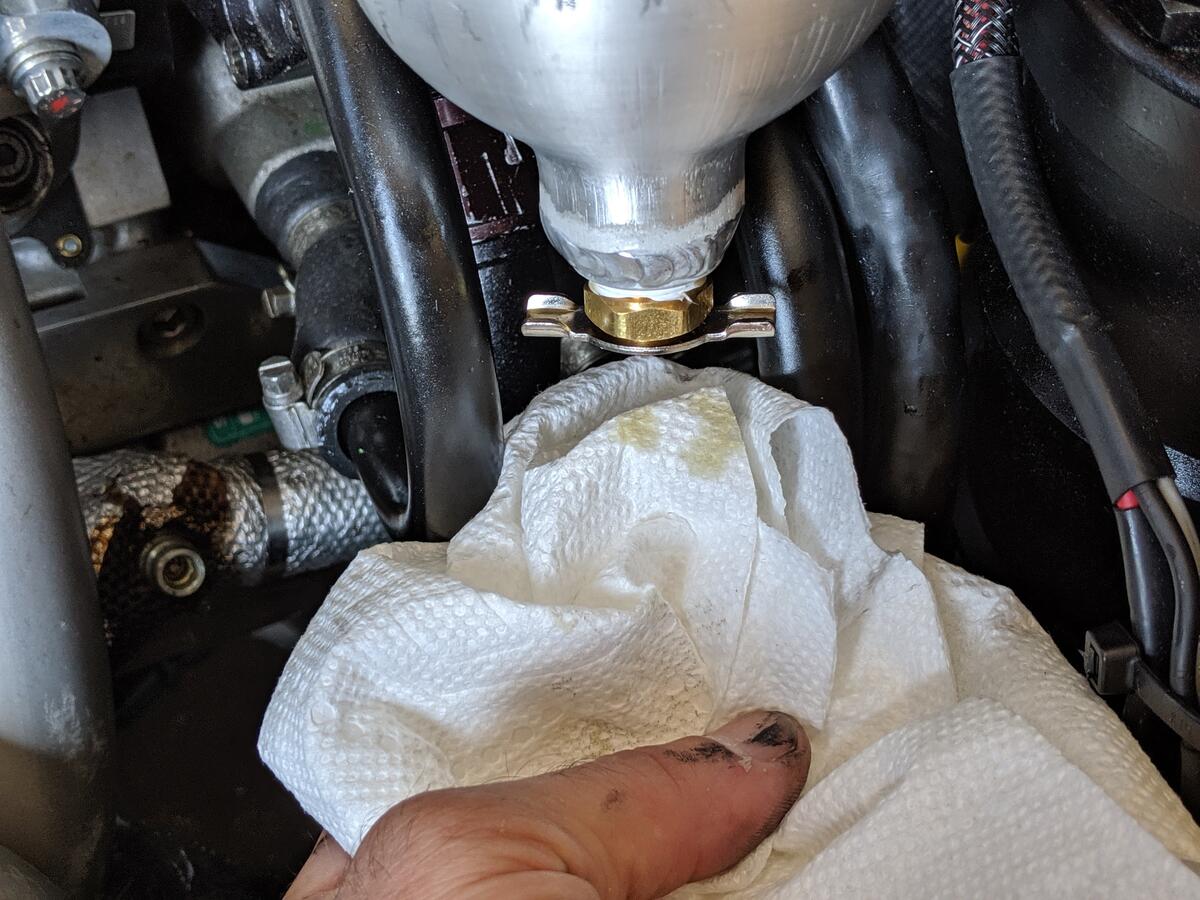
    Attached Thumbnails Attached Thumbnails Click image for larger version. 

Name:	IMG_20190808_111823.jpg 
Views:	600 
Size:	182.4 KB 
ID:	111204   Click image for larger version. 

Name:	IMG_20190808_111816.jpg 
Views:	602 
Size:	148.6 KB 
ID:	111205   Click image for larger version. 

Name:	IMG_20190808_111837.jpg 
Views:	610 
Size:	190.6 KB 
ID:	111206  

    Click image for larger version. 

Name:	IMG_20190808_111833.jpg 
Views:	621 
Size:	234.4 KB 
ID:	111207  

  14. #12
    Senior Member rodorico83's Avatar
    Join Date
    07.17.13
    Location
    Madrid, Spain
    Posts
    149
    Liked: 8

    Default

    Quote Originally Posted by jcolley View Post
    I had an Ultima GTR through the shop a couple of years ago with a really loosely built LS7. When it came in, the engine could would fill the oil sump breather catch can to overflow in less than 10 miles of driving.

    We went through a lot until we solved it.

    First off, since the scavenge pump will pull oil, air, small children...pretty much anything out of the oil pan, we blocked off the valve cover vents to reduce air coming in. Dyno showed a bit of gain pulling the crankcase to a light vacuum and this somewhat reduced the catch can oil filling. The owner was very concerned of over-vacuum on the crankcase so to ease his nerves, I installed a MAP sensor to monitor crankcase vacuum; side benefit is being able to monitor ring health in the long term.

    Finally, it occurred to me that since the engine had so much blowby being a very loose build, the single 8AN breather line from the sump tank to the catch can was seeing very high volumetric flow rate and entraining oil over to the catch can. My theory was, the small diameter breather was causing sufficient velocity to pull from the sump tank and larger/more diameter would reduce the gas velocity and keep the oil in the tank.

    We installed a much larger catch can with room for 3 10AN (!) hoses for venting. This seemed to work at idle, so off to WGI we went. I bet the owner it would be the end of the problem and told him I'd drink whatever came out of a 20 minute session.

    I was very relieved to be correct and not tethering myself to a toilet for a week, when he came off track there were only a couple of drops of oil that came out.

    In your case, even changing out the existing hose to a larger one allows the same volumetric flow rate with a lower velocity through it and might help.


    interesting...
    i ordered already 2l breather tank. i would do some tests with larger hoses and blocking heads ventilation, lets see how it behaves.

    thank guys

  15. #13
    Senior Member rodorico83's Avatar
    Join Date
    07.17.13
    Location
    Madrid, Spain
    Posts
    149
    Liked: 8

    Default

    also ill put wider and larger hose
    if bigger tank with bigger and larger hose does not work. I wonder if this type of tanks that are quite common ton these cars, that are placed directly on top of dry sump which i guess has an opening at the bottom with same size as the dry sump lid which in my case would be 10 cm opening !! but you have to do it yourself

    Attached Thumbnails Attached Thumbnails Click image for larger version. 

Name:	670978 (Small).jpg 
Views:	573 
Size:	107.8 KB 
ID:	111215  

  16. #14
    Contributing Member Rick Kirchner's Avatar
    Join Date
    02.24.02
    Location
    Tehachapi, CA
    Posts
    6,679
    Liked: 1630

    Default

    maybe I'm mis understanding things here - but the large "tower" on top of your tank is not any tank, it's the air/oil separator. Your oil enters from the scavenge stages tangentially into the tower, oil swirls into the tank below. there's usually a line off he top of this tower that takes the air into the overflow tank, and that tank is usually vented to the atmosphere, either through a filter or just a simple hose. You should draw out your entire oil/vent system and post, it will be a lot more informative.

  17. The following members LIKED this post:


  18. #15
    Senior Member
    Join Date
    01.21.12
    Location
    New Mexico USA
    Posts
    124
    Liked: 74

    Default Yes! to a schematic diagram

    Quote Originally Posted by Rick Kirchner View Post
    maybe I'm mis understanding things here - but the large "tower" on top of your tank is not any tank, it's the air/oil separator. Your oil enters from the scavenge stages tangentially into the tower, oil swirls into the tank below. there's usually a line off he top of this tower that takes the air into the overflow tank, and that tank is usually vented to the atmosphere, either through a filter or just a simple hose. You should draw out your entire oil/vent system and post, it will be a lot more informative.
    A schematic of the actual oil system configuration would certainly help the remote diagnosticians here on ApexSpeed. Noting on that schematic details [like hose inside diameters, content of lines (oil, scavenge oil, air), restrictors in any paths, etc.] would all be helpful.

    Lee

  19. #16
    Senior Member
    Join Date
    09.25.03
    Location
    near Athens, GA
    Posts
    1,739
    Liked: 1009

    Default

    Quote Originally Posted by Lee Johnson View Post
    A schematic of the actual oil system configuration would certainly help the remote diagnosticians here on ApexSpeed. Noting on that schematic details [like hose inside diameters, content of lines (oil, scavenge oil, air), restrictors in any paths, etc.] would all be helpful.

    Lee
    Agreed... be sure to include in your drawing, the 'inclination' of each line to/from anything. My limited experience (NOT INCLUDING DRY SUMP).. is that no 'vent line' should go 'downward' anywhere along the path to any catch tank. All vents need to be ABOVE and of sufficient internal diameter, to NOT ALLOW *FLUID* to be pushed through the pipe at any point. Any time fluid can FILL the line (whether tank or hose), it will create a 'gravity feed' (i.e. siphon) that will drag along any other fluid that can be found in the path. Even in a vee without dry sump, you can fill your overflow tank (and empty your sump) quite quickly if your 'vent line' is too small and catches a 'plug of fluid' that is pushed by blowby.. that pulls more fluid, that gets pushed, that pulls more ... etc, etc .. quickly.

    Some times you can test such a theory by making sure that there are open air vent holes at the top of any 'container' along the path. If it makes one helluva mess inside the bodywork.. you have your culprit. In reality there should be NO FLUID traveling along that path continuously. THAT's what the tanks are for.. to have the fluid enter a space so much larger than the travel path, that the fluid effectively 'atomizes' and drops the liquid bits.
    Steve, FV80
    Steve, FV80
    Racing since '73 - FV since '77

  20. #17
    Senior Member rodorico83's Avatar
    Join Date
    07.17.13
    Location
    Madrid, Spain
    Posts
    149
    Liked: 8

    Default

    Quote Originally Posted by Rick Kirchner View Post
    maybe I'm mis understanding things here - but the large "tower" on top of your tank is not any tank, it's the air/oil separator. Your oil enters from the scavenge stages tangentially into the tower, oil swirls into the tank below. there's usually a line off he top of this tower that takes the air into the overflow tank, and that tank is usually vented to the atmosphere, either through a filter or just a simple hose. You should draw out your entire oil/vent system and post, it will be a lot more informative.
    mmm yes in this case scanvenge hose leads to this tower, so for sure is open at the bottom , but i believe i saw also with the scanvege leading to dry sump instead.
    this was an example of what can be done also

  21. #18
    Senior Member rodorico83's Avatar
    Join Date
    07.17.13
    Location
    Madrid, Spain
    Posts
    149
    Liked: 8

    Default

    here a drawing.
    the inclinations of hoses can be seen more less in pics. the hose that is sucking oil (as i never saw any oil in the 15mm vent hose) is the drain hose (blue) with 10mm internal diameter but with around 6mm ID AN fitting on dry sump side, this hose has a slighly down inclination in some part as pic, vent hose from dry sump to tank has a bit downward inclination also.

    Im gonna update drain hose with 15mm hose and high flow fittings, and try to dont be downward along all path and increase tank to 2 litres.

    Attached Thumbnails Attached Thumbnails Click image for larger version. 

Name:	1715632288990 (Small).jpg 
Views:	519 
Size:	50.8 KB 
ID:	111230  

  22. #19
    Contributing Member Rick Kirchner's Avatar
    Join Date
    02.24.02
    Location
    Tehachapi, CA
    Posts
    6,679
    Liked: 1630

    Default

    So going back and looking at your pics, and this diagram, it appears your setup dumps the scavenge, full of air, into the side of the tank. if the scavenge line gets below the oil level in the tank I can't think that would be good.

    If you look around on this site or any other race car sales sites for pics of Indy Lights cars for sale (the US equivalent of F3000) you'll see that most of them have a separator tower where your car has a plate with that vent/drain line in it. So does virtually every FF/FC/FA on this site that was built with an integral bell housing/oil tank.

    Is this car a Reynard, Lola, or March? Seems like there are some resources out there that would show the proper oil system schematic.

    This is not uncommon. I had an acquaintance blow up a BDA 3 TIMES! before he figured out he had scavenge and pressure lines reversed.

    https://www.race-cars.com/content/Us...744729.jpg?v=1

  23. #20
    Senior Member rodorico83's Avatar
    Join Date
    07.17.13
    Location
    Madrid, Spain
    Posts
    149
    Liked: 8

    Default

    Quote Originally Posted by Rick Kirchner View Post
    So going back and looking at your pics, and this diagram, it appears your setup dumps the scavenge, full of air, into the side of the tank. if the scavenge line gets below the oil level in the tank I can't think that would be good.

    If you look around on this site or any other race car sales sites for pics of Indy Lights cars for sale (the US equivalent of F3000) you'll see that most of them have a separator tower where your car has a plate with that vent/drain line in it. So does virtually every FF/FC/FA on this site that was built with an integral bell housing/oil tank.

    Is this car a Reynard, Lola, or March? Seems like there are some resources out there that would show the proper oil system schematic.

    This is not uncommon. I had an acquaintance blow up a BDA 3 TIMES! before he figured out he had scavenge and pressure lines reversed.

    https://www.race-cars.com/content/Us...744729.jpg?v=1
    is a lola b99. indeed most of them have this tower but i also saw different setups with separate tank.
    in fact gearbox has inlet for scanvege which is the one im using, you can see in black in dry sump pic on top of input shaft cover.
    these towers with scanvege inlet how are inside ?? i guess scanvege inet inside tower has pipe to direct fluid down ??
    are these towers base fully open to dry sump ??
    i guess these are custom made and there is no way to get it from somewhere ??

  24. #21
    Contributing Member Rick Kirchner's Avatar
    Join Date
    02.24.02
    Location
    Tehachapi, CA
    Posts
    6,679
    Liked: 1630

    Default

    My guess is that its a standard par that has been replaced. The oil usually enters tangentially, swirls down the sides and loses entrapped air as it goes.

    When I was looking for pics I stumbled across this post, might be some similarities here:
    https://www.apexspeed.com/forums/sho...ghlight=lights

  25. #22
    Senior Member rodorico83's Avatar
    Join Date
    07.17.13
    Location
    Madrid, Spain
    Posts
    149
    Liked: 8

    Default

    something like this can be an option
    https://ahfabrications.co/store/oil-...aeration-head/

    and some documentation about it

    https://dspace.cvut.cz/bitstream/han...vicova_kos.pdf
    Last edited by rodorico83; 05.14.24 at 6:00 PM.

  26. #23
    Senior Member rodorico83's Avatar
    Join Date
    07.17.13
    Location
    Madrid, Spain
    Posts
    149
    Liked: 8

    Default

    been thinking how to make this easy and efficient ...
    what do you think of the following?
    from top to bottom of tower as follow (10cm rounded can)
    cap, inside: cap stainless steel scourers and vent outlet at same level, under it baffle plate with 25cm hole in the middle or small holes close to the middle under baffle , under it engine breather inlet and about 2 or 3 cm below scanvege inlet tangetial and a couple of degree pointing down. tank open at the bottom and bolted to gearbox

Thread Information

Users Browsing this Thread

There are currently 2 users browsing this thread. (0 members and 2 guests)

Posting Permissions

  • You may not post new threads
  • You may not post replies
  • You may not post attachments
  • You may not edit your posts
  •  


About Us
Since 2000, ApexSpeed.com has been the go-to place for amateur road racing enthusiasts, bringing together a friendly community of racers, fans, and industry professionals. We're all about creating a space where people can connect, share knowledge, and exchange parts and vehicles, with a focus on specific race cars, classes, series, and events. Our community includes all major purpose-built road racing classes, like the Sports Car Club of America (SCCA) and various pro series across North America and beyond. At ApexSpeed, we're passionate about amateur motorsports and are dedicated to helping our community have fun and grow while creating lasting memories on and off the track.
Social