Results 1 to 22 of 22
  1. #1
    Member
    Join Date
    11.10.14
    Location
    Northern California
    Posts
    44
    Liked: 7

    Default Another Build on the horizon

    Hi Everyone

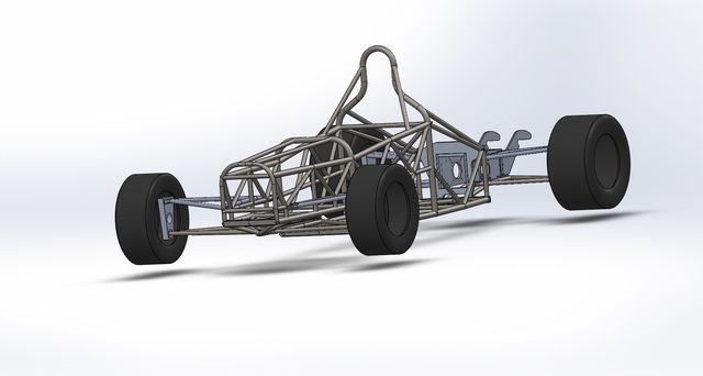
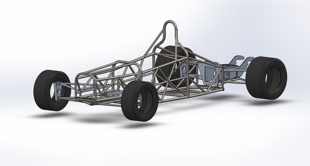
    And "Thanks for all the information". Been lurking here for months reading every thing many of you have been kind enough to share. Looking for help and opinions on a build prior to my starting to cut and weld tube for an F1000.

    Pretty much too old to seriously consider myself any thing like a serious driver. Although I have been around SCCA, NHRA, and D1 racing for years fabing up cages and machining parts for what seems like decades. All the while never owning a car myself.

    This one I intend to be for me.
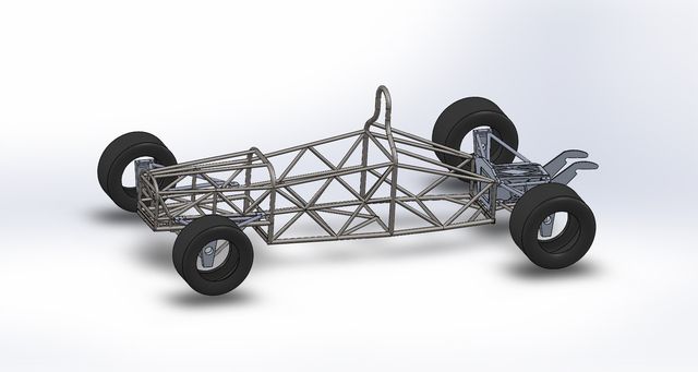


  2. The following members LIKED this post:


  3. #2
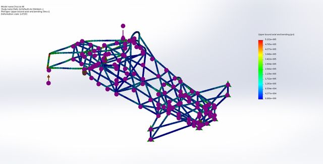
    Grand Pooh Bah Purple Frog's Avatar
    Join Date
    04.03.01
    Location
    Havana, Fl, USA
    Posts
    10,811
    Liked: 3874

    Default

    Check GCR, but I think you need forward facing rollhoop supports or an Engineer's certificate saying you don't.


  4. #3
    Member
    Join Date
    11.10.14
    Location
    Northern California
    Posts
    44
    Liked: 7

    Default

    Thanks for the heads up.

    Just how detailed would the engineering report have to be? I have access to several mechanical engineers who would be willing to help me out with that.

    And Yes - there are still a couple of details not in the drawing

    For 1 the "Uprights" are essentially crude block diagrams. I run my mill on an older CAM software that doesn't import well. I'll be finalizing the design of the Uprights on that once a few more parts arrive.

    Additionally I have been having trouble with the GSXR 1000 Engine model I acquired from "Grab-Cad" so the differential side plates are incomplete as well

  5. #4
    Senior Member
    Join Date
    01.11.05
    Location
    Zionsville, Indiana
    Posts
    3,178
    Liked: 1428

    Default

    The GCR requires that the roll bar be braced from a maximum of 6 inches below the top of the main hoop. The braces must be a minimum of 1" diameter x .080 wall. And those braces must go forward. Also the included angle between the forward brace and the main hoop must be 30 degrees or greater. Also the base of the roll bar has to be 15" between the 2 legs of the main hoop.

    The GCR also spells out the requirements that an engineer must certify, if you do not build a roll hoop according to the GCR. The numbers are based on the weight of the car but are loads exerted on the roll hoop structure in the longitudinal. lateral and vertical planes simultaneously.

    On one of my cars, I have two hoops shaped much like yours but the main hoop angles forward from the rear bulkhead and the brace is just behind the drivers head as you main hoop is now. The two hoops attach at the top. The angle between the 2 hoops is more than 30 degrees, and the main hoop attached to the rear bulkhead with more than 15 inches between the two sides where it attaches.

  6. #5
    Senior Member
    Join Date
    08.18.02
    Location
    Indy, IN
    Posts
    6,345
    Liked: 1968

    Default

    Quote Originally Posted by S Lathrop View Post
    Also the base of the roll bar has to be 15" between the 2 legs of the main hoop.

    Just to clarify, the 15 inches is at the point were the main hoop attaches to the main frame rails.

    Also, if you use an engineer to certify and alternative design, it has to be a licensed engineer, and to the specs outlined in the GCR.

  7. #6
    Member
    Join Date
    11.10.14
    Location
    Northern California
    Posts
    44
    Liked: 7

    Default

    Thanks for the replies guys

    Correct me if I'm wrong but "the vertical members of the main hoop shall not be less than 15 inches apart (inside dimension) at their attachment to the chassis." are minimum distances. - At 20" I think I'm ok there

    I'm still reworking the chassie to include the needed forward supports

    Thanks


  8. #7
    Senior Member
    Join Date
    01.11.05
    Location
    Zionsville, Indiana
    Posts
    3,178
    Liked: 1428

    Default

    Quote Originally Posted by JoeFin View Post
    Thanks for the replies guys

    Correct me if I'm wrong but "the vertical members of the main hoop shall not be less than 15 inches apart (inside dimension) at their attachment to the chassis." are minimum distances. - At 20" I think I'm ok there

    I'm still reworking the chassie to include the needed forward supports

    Thanks
    I got the Homologation papers on my FV in 1994. I made both hoops mount with 15 between the 2 legs. The GCR wording has changed since then. More importantly, the people in the office at SCCA do not have the understanding of the rules that the people in Denver had. In short, the same structure that the CRB approved in 1994 and made the comment that they liked my alternative better than what I could to meet the letter of the rules, Topeka made me get an engineers certification at no small expense.

    If you read what you wrote in red, I venture that there is not a single tube frame formula car that meets that rule. For sure, no car that I have ever built meets what you have high lighted in red. I can not think of any car that I have ever seen that has the roll bar bent so that the portion of the bar just above the mount is vertical. They usually terminate at an angle to the point they attach.

    Here is a picture of something that you might consider.

  9. #8
    Grand Pooh Bah Purple Frog's Avatar
    Join Date
    04.03.01
    Location
    Havana, Fl, USA
    Posts
    10,811
    Liked: 3874

    Default

    Many ways to skin the cat.

    Last edited by Purple Frog; 11.08.16 at 12:24 AM.

  10. The following members LIKED this post:


  11. #9
    Member
    Join Date
    11.10.14
    Location
    Northern California
    Posts
    44
    Liked: 7

    Default

    forward braces added tp the main hoop


  12. #10
    Senior Member
    Join Date
    08.18.02
    Location
    Indy, IN
    Posts
    6,345
    Liked: 1968

    Default

    Putting the braces to the center of an unsupported tube is about as useless as... well, you know.

    I'd have to go re-read the rules again to see if that would even be legal.

  13. #11
    Contributing Member Jtovo's Avatar
    Join Date
    05.01.01
    Location
    Chicago, IL
    Posts
    1,241
    Liked: 79

    Default


  14. #12
    Senior Member
    Join Date
    01.11.05
    Location
    Zionsville, Indiana
    Posts
    3,178
    Liked: 1428

    Default

    JoeFin.

    Try to model you frame with a static load applied the bottom of the front uprights, say 1000 lbs. up on one side and down on the other side. Anchor the car with the rear suspension, maybe the rear bulkhead.

    Your simulation program should give you a number for how much the frame moves under the load. You can take that number and calculate the spring rate for your chassis as foot pounds per degree.

    Bad for a F1000 would be 2000 ft. lbs. per degree great would be 10,000. When I tested a Swift 008 I got 8000. You will be running FA times so you want to think in terms of an FA.

  15. #13
    Member
    Join Date
    11.10.14
    Location
    Northern California
    Posts
    44
    Liked: 7

    Default

    Quote Originally Posted by S Lathrop View Post
    JoeFin.

    Try to model you frame with a static load applied the bottom of the front uprights, say 1000 lbs. up on one side and down on the other side. Anchor the car with the rear suspension, maybe the rear bulkhead.
    That's what I'm working on now

    I finished the changes to the chassis to include the required bracing. The changes were significant enough to re-analysis the chassis again too. I'm using 2500 lbs each side opposing. Right now my mesh is not working out so it will have to wait for Friday when I have more time to devote to this.

    And I was under the impression 5000 lbs per degree was the target from reading prior post on this subject. That was what the original chassis was designed to.

    Wish I had more time to devote to this but I still hold a full time job, have a wife, and 2 brats in college to deal with. But I did complete my frame welding jig, and 80% on the bending dies for 5" radius 1.375" tube


    Last edited by JoeFin; 04.09.15 at 6:26 AM.

  16. #14
    Contributing Member Jnovak's Avatar
    Join Date
    12.08.07
    Location
    Dearborn, Michigan
    Posts
    3,787
    Liked: 896

    Default

    Quote Originally Posted by JoeFin View Post
    That's what I'm working on now

    I finished the changes to the chassis to include the required bracing. The changes were significant enough to re-analysis the chassis again too. I'm using 2500 lbs each side opposing. Right now my mesh is not working out so it will have to wait for Friday when I have more time to devote to this.

    And I was under the impression 5000 lbs per degree was the target from reading prior post on this subject. That was what the original chassis was designed to.

    Wish I had more time to devote to this but I still hold a full time job, have a wife, and 2 brats in college to deal with. But I did complete my frame welding jig, and 80% on the bending dies for 5" radius 1.375" tube


    Imo, 5000 ft-lbs/degree is a very good target. This is not easy to achieve over the full length of the chassis, suspension to suspension.
    Thanks ... Jay Novak
    313-445-4047
    On my 54th year as an SCCA member
    with a special thanks to every SCCA worker (NONE OF US WOULD RACE WITHOUT THE WORKERS)

  17. #15
    Member
    Join Date
    11.10.14
    Location
    Northern California
    Posts
    44
    Liked: 7

    Default

    Can anyone tell me if I'm reading this right. I believe this satisfies the 1 Deg / 5000 ftlbs design spec. The upper portions of the main roll hoop move a bit but the lower rails of the chassis are less then the 1 Deg / 5000 ftlbs goal


  18. #16
    Contributing Member Jnovak's Avatar
    Join Date
    12.08.07
    Location
    Dearborn, Michigan
    Posts
    3,787
    Liked: 896

    Default

    Joe, I note that your loads and constraints are at the upright and this is fine. How are the loads transfered to the chassis?

    I do not see pushrods, rockers, or shock replacement rods in your model

    For instance if you were actually doing a torsional test on a completed assembled chassis you would replace the shocks with solid rods and then apply the loads to the uprights.

    Another way is to constrain the front or the rear of the chassis with a simple rigid fixture and the apply a torsional load at the other end. This is actually easier but generally produces torsional stiffness numbers that should be used as guidelines as opposed to some sort of number that you might publish in a report, as in, is it stiffer now that I have changed the chassis design in some way.

    When I was very much into modeling and testing we would ALWAYS test a chassis after it had been modeled to correlate the modeling work.

    There are many ways to do torsional stiffness models and it looks like you are heading in the right direction. The constraints you use in a model are very critical in determining if your model reflects reality.
    Thanks ... Jay Novak
    313-445-4047
    On my 54th year as an SCCA member
    with a special thanks to every SCCA worker (NONE OF US WOULD RACE WITHOUT THE WORKERS)

  19. #17
    Senior Member
    Join Date
    01.11.05
    Location
    Zionsville, Indiana
    Posts
    3,178
    Liked: 1428

    Default

    Joe;

    I anchor my models at the rear and load the fronts. I do the actual cars the same way. Just to light the model up, I use 1000 lbs. force at the bottom of the upright on each side of the front. One side is up and the other is down. You can then look at the displacement at the loaded points and calculate the ft. lbs. per degree load you simulated.

  20. #18
    Member
    Join Date
    11.10.14
    Location
    Northern California
    Posts
    44
    Liked: 7

    Default

    Yes JNovak

    The chassis model is overly simplified to allow many rapid changes to find out what works and what don't. I now have to go back and include the Strong-Back and Differential housing to see how that is going to hold up as well but thankfully I'm making progress.

    And yes Mr Lathrop - I did try several combinations of anchor points as I went along. Worked out pretty good to help me address all the various stress points in the chassis

  21. #19
    Senior Member JJLudemann's Avatar
    Join Date
    04.14.10
    Location
    Thailand
    Posts
    168
    Liked: 36

    Default Re: Solidworks chassis FEA model

    Your photo is just a little too low-res for me to read the labels. Is that a plot of displacement? What are the loads and maximum displacements? I think something may be wrong if you're getting acceptable stiffness numbers upright to upright, as I don't see pushrods. You need to model the pushrods with a solid mount on the inboard end to transfer the upright loads to the chassis. If the A-arms are just acting as cantilevered beams, your model should show very low stiffness.

    -Jim

  22. #20
    Senior Member jchracer's Avatar
    Join Date
    01.25.12
    Location
    Florida
    Posts
    375
    Liked: 279

    Default

    As the other posters have said, there are a few things you need to do to get meaningful results. Adding the push-rods is number one. I would also add the bell-cranks, shocks, and take a stab at the how those components are located to the frame. I have seen awful designs (mostly cantilevered, single shear mounts) that added significant flexibility to the system. Special care should be given to all the beam ends where the actual car will have spherical or rotational joints. Most beam FEA programs have a “beam release” function where a spherical or rotational joint can be simulated. The overall model should be “kinematically costrained”, sometimes called a 321 constraint within the FEA community. Google those terms and you will find some help.
    Last edited by jchracer; 04.24.15 at 1:53 PM.
    Ciao,

    Joel
    Piper DF-5 F1000

  23. #21
    Member
    Join Date
    11.10.14
    Location
    Northern California
    Posts
    44
    Liked: 7

    Default

    Thanks guys

    I'm "Babysitting" the start up of a couple 100Meg Turbine/Generators for the next couple nights so I don't know how much I'll get done on my laptop. At 8 Gig memory its a little "Whimpy" and pretty much "Click and Wait", but I'll add the recommended items a re-run some test

    Should be interesting

  24. #22
    Member
    Join Date
    11.10.14
    Location
    Northern California
    Posts
    44
    Liked: 7

    Default Still plugging along

    Haven't had much time to work on this as I had to work a project that required 7-12 hr days a week since last Aug. Just now have been able to come up for air and got a little cherished shop time to work out a few details.

    Anyway here is my shot at putting together the uprights for my build


Thread Information

Users Browsing this Thread

There are currently 1 users browsing this thread. (0 members and 1 guests)

Posting Permissions

  • You may not post new threads
  • You may not post replies
  • You may not post attachments
  • You may not edit your posts
  •  


About Us
Since 2000, ApexSpeed.com has been the go-to place for amateur road racing enthusiasts, bringing together a friendly community of racers, fans, and industry professionals. We're all about creating a space where people can connect, share knowledge, and exchange parts and vehicles, with a focus on specific race cars, classes, series, and events. Our community includes all major purpose-built road racing classes, like the Sports Car Club of America (SCCA) and various pro series across North America and beyond. At ApexSpeed, we're passionate about amateur motorsports and are dedicated to helping our community have fun and grow while creating lasting memories on and off the track.
Social