Results 1 to 29 of 29
  1. #1
    Senior Member sidney's Avatar
    Join Date
    01.14.05
    Location
    Ames, IA
    Posts
    413
    Liked: 0

    Default Bolt In Structure for Late Model VD

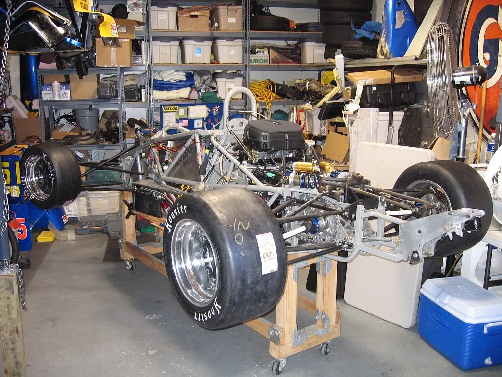
    Below is the latest iteration of my bolt-in structure design. It will allow for all stock suspension hardware from a late model '97 and up VD to be used without modification. The other benefit is it uses a differential from a VW rabbit, so the cost is much lower than something from TRE. If you really want a torque bias diff, you can get one from Peloquins for about half of what a Quaife integral unit costs. I plan on having top, bottom and rear plates helping stiffen the structure, but have left these off the model so you can see the internal areas. I'm also working on a similar structure for earlier vintage VDs.
    Attachment 2664
    Last edited by sidney; 07.04.07 at 8:54 AM.
    Ian MacLeod
    "Happy Hour: 5:00 - 5:30"
    Tatuus F1k

  2. #2
    Senior Member Stan Clayton's Avatar
    Join Date
    11.14.03
    Location
    Mooresville NC area
    Posts
    4,157
    Liked: 309

    Default

    Very nice, Sidney! Do you plan to offer these for sale?

    Stan
    Stan Clayton
    Stohr Cars

  3. #3
    Senior Member
    Join Date
    01.03.05
    Location
    Redford,Michigan
    Posts
    136
    Liked: 8

    Default VD rear structure

    Ian,sorry, Sidney,Youve cleaned your design up a lot,it looks good,what is your game plan?

    Dave Craddock

  4. #4
    Senior Member sidney's Avatar
    Join Date
    01.14.05
    Location
    Ames, IA
    Posts
    413
    Liked: 0

    Default Game Plan

    Thanks for the positive comments. I beleive this is interation number 47, I lost revision count a while ago. The first of these is currently being fabricated using 4130. I have 2D prints of every tube needed to make one. If there is interest, we will offer these for sale. Probably without mounting tabs for the engine, however, if this is needed, I'm sure we can work something out. I'd also be iterested in "licensing" the design if someone would like to make their own. My father and I are working on a very tight budget, and I am very much a part of the F1k trend to cut costs and spend more weekends at the track. I'm also working on a plan to produce a similar design for the '96 and down VDs. It's a process of working out the prints and reducing the length of the bell housing area of the design.

    Our personal gameplan is to hopefully procure a '98 or up VD after the runoffs and convert to F1k over the next 12-18 months. We have not determined a powerplant as of yet, so the mounting ears are not fixed on the front of the structure.

    We've been playing with the idea of producing a motorcycle FC car since '85. We have 2 1985 VF 1000R motors in the garage! Problem is, back then it produced about 130 hp. Don't know anybody who wants to buy some vintage Honda hardware?

    Ian MacLeod
    (Sidney's the dog's name, but it's an easy and different ID to use on the 'net)
    Ian MacLeod
    "Happy Hour: 5:00 - 5:30"
    Tatuus F1k

  5. #5
    Senior Member sidney's Avatar
    Join Date
    01.14.05
    Location
    Ames, IA
    Posts
    413
    Liked: 0

    Default Another One fromthe Blimp Cam

    Here's another shot from a top view perspective. Using some math, I have calculated the mass of the structure to be about 43 pounds, without the differential and it's bearing carriers. The stock diff is about 13 pounds, and the carriers will add another 2. The design is angled at 6.5 degrees. It will require custom, equal length axles. The main reason for focusing on the '98 and up cars was for the flexability of all the bolt-on rear end. I have to give credit to Mike Beauchamp for part of this design. I wan't really sold on the angled diff until some conversations we had concerning the subject. I guess if it's good enough in a Speads CSR putting 240+ hp down, it should be good enough for F1k.
    Attachment 2667
    Last edited by sidney; 07.04.07 at 8:54 AM.
    Ian MacLeod
    "Happy Hour: 5:00 - 5:30"
    Tatuus F1k

  6. #6
    Contributing Member
    Join Date
    09.11.02
    Location
    Williamsburg, VA
    Posts
    194
    Liked: 17

    Default Diff at angle

    Speads solution of using the diff at an angle is elegant, BUT, cars are having adnormal failure rate of the the inboard CV joint. (I am a former owner). Too many failures for basically a new car. THe SR versions use the standard type CV, one off a UK Ford FWD. THe formula Speads cars uses a robust, Internation Harvester looking universal joint and haven't heard of any failures, so far. Ed Dickinson has put quite a few miles on his Speads FS with a GSXR without problems.

  7. #7
    Global Moderator carnut169's Avatar
    Join Date
    01.22.02
    Location
    Atlanta, Ga
    Posts
    3,700
    Liked: 11

    Default

    FWIW on my 96 we had to cut at the firewall as the GSXR was just a hair too wide to fit in the factory framework. Not sure the bolt-on approach will work in all of the older cars. HOWEVER, offering the back end does give the builder a huge leg-up since workig with suspension pick-ups, etc was a ton of work.
    Sean O'Connell
    1996 RF96 FC
    1996 RF96 FB
    2004 Mygale SJ04 Zetec

  8. #8
    Senior Member sidney's Avatar
    Join Date
    01.14.05
    Location
    Ames, IA
    Posts
    413
    Liked: 0

    Default West has it figured out

    I agree that the motor may be a little too wide to fit into the space provided by the existing chassis. That's why the bolt-in solution that the '98 and up cars provide is slick. No cutting, just a couple of extra tubes that bolt to the rear of the firewall. I envision something similar to what they do on the West cars.

    Attachment 2672
    Last edited by sidney; 07.04.07 at 8:54 AM.
    Ian MacLeod
    "Happy Hour: 5:00 - 5:30"
    Tatuus F1k

  9. #9
    Member
    Join Date
    09.23.03
    Location
    US
    Posts
    39
    Liked: 0

    Default built one

    98 or newer based.

  10. #10
    Global Moderator Mike B's Avatar
    Join Date
    12.03.00
    Location
    Green Bay, WI
    Posts
    3,798
    Liked: 710

    Default

    Is that welded to the chassis? Doesn't that defeat the modularity of the newer chassis?
    What diff did you use?
    Oh yeah, your roll hoop is on backwards...
    Mike Beauchamp
    RF95 Prototype 2

    Get your FIA rain lights here:
    www.gyrodynamics.net/product/cartek-fia-rain-light/

  11. #11
    Member
    Join Date
    09.23.03
    Location
    US
    Posts
    39
    Liked: 0

    Default reply

    yes its welded to the original. Why. different geomety of a bike engines would complicate tyring to pic up the VD mounts. the modualarity comes aft of the motor. all suspension and associated space frame aft of engine bay unbolt. Oh my god ! the roll hoop is on backwards!! -- throw the F#%&ing thing away I guess.

  12. #12
    Senior Member sidney's Avatar
    Join Date
    01.14.05
    Location
    Ames, IA
    Posts
    413
    Liked: 0

    Default R1 Motor?

    This looks very nicely done, except for the roll hoop. Is that an R1 motor? Are you planning on running this car in F1k for '07 or is it just for fun? The other issue I tried to solve with my design was equal length axles. What diff are you using? I know Mike B was looking at a Honda diff, I put a VW in my design, mostly because my old man has an endless supply source. Are you the same Mike I sent all the dimensional info to for the DSRs? Hopefully this discussion will lead to more folks sharing their concepts/work. I'm here to learn, and hopefully, in the near future, race one of these babys!
    Ian MacLeod
    "Happy Hour: 5:00 - 5:30"
    Tatuus F1k

  13. #13
    Member
    Join Date
    09.23.03
    Location
    US
    Posts
    39
    Liked: 0

    Default reply

    Not the same mike but same project. The diff is honda based w/unequal length drive shafts. Motor GSXR. Planning on running the Car THIS Year in DSR trim. However , this design will work for FS. I would think it would run very strong in FS.

  14. #14
    Global Moderator Mike B's Avatar
    Join Date
    12.03.00
    Location
    Green Bay, WI
    Posts
    3,798
    Liked: 710

    Default

    Mike,
    Is that a readily-available diff or a custom job? LSD or open?
    Keep the roll hoop the way it is, it looks cool.
    Mike Beauchamp
    RF95 Prototype 2

    Get your FIA rain lights here:
    www.gyrodynamics.net/product/cartek-fia-rain-light/

  15. #15
    Contributing Member Mike Devins's Avatar
    Join Date
    12.05.03
    Location
    Romeo, Michigan
    Posts
    872
    Liked: 29

    Default Dif for VD new chassis conversion

    The dif is a Quaiffe - Honda B-16 that they make for chain drive applications. Alot of them are used by the FSAE guys. I make the bearing carriers and the sub shafts were made by Taylor and will support either the 26 or 40mm tripod or the CV that VD used on there cars.

    Chain adjustmen is done by shimming the carrier out from the X-member that also supports the rockers for the shocks.

    As for the portion of the chassis that is now welded to the original front section. This was not our first choice but the reality is that none of the VD pickup points really worked well with the MC engine and having the motor load from the top started making the chassis too wide.

  16. #16
    Contributing Member
    Join Date
    08.27.05
    Location
    Sherman Oaks CA
    Posts
    164
    Liked: 0

    Default

    Quote Originally Posted by sidney
    Hopefully this discussion will lead to more folks sharing their concepts/work. I'm here to learn, and hopefully, in the near future, race one of these babys!
    Hear hear.
    Maybe one day I can give an older RF a kick in the pants too!
    In the meantime, this, for me, is what racing is about. Tinkering -- ahem, car design --is a heck of a lot of fun!
    Chris Leong
    Team 5150
    Lynx Solo Vee

  17. #17
    Senior Member
    Join Date
    11.30.05
    Location
    Ann Arbor, MI
    Posts
    127
    Liked: 0

    Default

    For the older cars the SE3, VD85, VD86 are all too narrow and will have to be cut off at the roll hoop. I tried the Suzuki GSXR1000 motor in all of them, none fit, frame tubes are too narrow.
    The purpose built cars use tubes that are lower and higher then the main width of the engine, on the right side of the engine slots under that side tube. My OMS with a ZX11 motor in it does it this way. It has an offset diff and unequal length driveshafts.
    I also had a Jedi with a ZX10 motor - it had 2mm clearance from clutch cover to the side frame spar, diff offset 5 inches to the left of the car.

    Cheers
    David

  18. #18
    Contributing Member RussMcB's Avatar
    Join Date
    03.19.02
    Location
    Palm Coast, FL
    Posts
    6,682
    Liked: 553

    Default

    Hey, I'd like to kickstart this thread, 'cause it's got some neat ideas.

    Any progress with someone building or offering plans for a rear subframe with suspension points and diff?
    Racer Russ
    Palm Coast, FL

  19. #19
    Contributing Member Mike Devins's Avatar
    Join Date
    12.05.03
    Location
    Romeo, Michigan
    Posts
    872
    Liked: 29

    Default Rear sub-frame

    Russ,

    I will be happy to help out with the rear sub - It uses all RF98 and newer geometry. Pat Prince also does a conversion for the RF92 thru RF96.

    I also know that couple of others including Duanne Dykeman have been working on conversions for the older Van Dieman chassis.

    Pictures of my frame are attached to Mike Sirianni's reply earlier in this thread

    Mike Devins
    hrp-llc@comcast.net

  20. #20
    Contributing Member RobLav's Avatar
    Join Date
    12.05.00
    Location
    Somerset, Kentucky
    Posts
    2,914
    Liked: 126

    Default

    I'm studying this issue with my RF99 and a 2006 Yamaha R1. Think I've got it about figured out. Problem with that R1 is that the sprocket is just about the same height as the left rear upper A-Arm forward leg. The lower left A-Arm rear leg will not be a problem by raising the differential about 1". This also better aligns the driveshafts with the height of the uprights. The 2006 R1 is nice and narrow... It will not be a simple bolt in conversion. The way I see it, there has to be a couple brackets welded to the top of the chassis at the rear roll hoop outer edges to attach tubes to - that run down to the bottom floor and the bottom of "the box" while picking up a bracket at the head. Those brackets will easily be inside the current bodywork.

    Am thinking of making this box out of 1" and 1" by 2" square / rectangular tubing with aluminum stressed panels. This would be legal by the last rules version I saw. The weight of that box plus the Quaife must be about the same weight as the VD bell in order to get to min weight.

  21. #21
    Contributing Member Mike Devins's Avatar
    Join Date
    12.05.03
    Location
    Romeo, Michigan
    Posts
    872
    Liked: 29

    Default RF Conversion

    Rob,

    What were you planning on using for a Dif? I used a Quaife (honda B-16), in order to clear the lower rear pick up point the dif had to be moved to the right. Either the motor has to move with it or the engine has to be at an angle in the frame. We opted to rotate the engine.

    Mike Devins

  22. #22
    Global Moderator carnut169's Avatar
    Join Date
    01.22.02
    Location
    Atlanta, Ga
    Posts
    3,700
    Liked: 11

    Default

    You all know how we did my car... I've been fighting axle-angle issues and have gone through more tripod assemblies this year than anyone would in a lifetime.


    well here are some of the changes we are currently working on:

    Pat Prince has my lower rear wishbones. We are moving the aft leg back 2.5"- exactly the amount between the bolt holes on the brackets for the lower a-arm aft mounts. This will allow the same bracket (for aft leg & toe mounts) to "slide" back and the hole in the aft portion of the bracket will now be attached in the front of the bracket. New hole has to be drilled w/ a sleeve welded in.


    1. Diff assembley slides on top of the lower rails in back and bolts to slides with notches in the middle. With the diff moved back 2" the slides will have to be moved- cut off and re-welded (4 total)


    2. About 2" of the diff assembly needs to be cut off (each side) and a new hole drilled- you can see it will run into the vertical rail now. Second pic shows that pretty good. We are going to adapt the new VD style "diff holders" to adjust the carrier (chain tension).

    3. Idler sprocket. Hole drilled in vertical rail with supporting bracket welded to the frame to attach the pictured pulley. Has to be strong. This will keep the chain off the forward leg of the left rear lower a-arm.


    Sean O'Connell
    1996 RF96 FC
    1996 RF96 FB
    2004 Mygale SJ04 Zetec

  23. #23
    Contributing Member RussMcB's Avatar
    Join Date
    03.19.02
    Location
    Palm Coast, FL
    Posts
    6,682
    Liked: 553

    Default

    Quote Originally Posted by Mike Devins
    <snip> I used a Quaife (honda B-16), in order to clear the lower rear pick up point the dif had to be moved to the right. Either the motor has to move with it or the engine has to be at an angle in the frame. We opted to rotate the engine.
    Mike, that's intereresting. If the rear sprocket is inside the structure that contains the suspension pick up points, then a lot of the issues Sean has faced would not be a factor. I think that's what the Gloria cars have done. I think they have shorter suspension arms that help (compared to longer VD arms).

    It sounds like several people have gotten comfortable with the idea of a slanted engine. When you came to that conclusion, was it partially because moving the entire engine to the right was deemed undesireable? From looking at Sean's pictures, it looks like maybe a 2" move might have been enough to get the chain on the inside of the rear suspension and resolve all of the clearance issues related to those components. Would moving the engine 2" to the right and leaving it 100% in line with the car (as opposed to slanted) have caused new issues that you didn't want to tackle?

    From a COG POV, since we often race clockwise, the shifted engine might not be a bad thing.

    I can't remember if the attached picture is a Gloria or a Stohr or what. It has a solid rear axle, I think.

    Russ
    Last edited by RussMcB; 10.10.09 at 12:26 PM.
    Racer Russ
    Palm Coast, FL

  24. #24
    Contributing Member formulasuper's Avatar
    Join Date
    08.17.03
    Location
    Marietta,Ga.
    Posts
    2,710
    Liked: 61

    Default

    Russ, This frame work would make for a wider engine compartment than most formula cars originally have. Not a problem unless you are trying to reuse the original bodywork. I agree that the frame design & engine/tranny/diff installation are the top priority, with body work then being made to fit the final assembly.
    Scott Woodruff
    83 RT5 Ralt/Scooteria Suzuki Formula S

    (former) F440/F5/FF/FC/FA
    65 FFR Cobra Roadster 4.6 DOHC

  25. #25
    Senior Member sidney's Avatar
    Join Date
    01.14.05
    Location
    Ames, IA
    Posts
    413
    Liked: 0

    Default 98+ VD layout

    IF someone wants the tubing plans for my design listed above, as I now have a Tatuus to convert, new plans have been developed. I can fax them to anybody who wants them. email me at imacleod@sauer-danfoss.com and I'll send it out via PDF.

    Ian
    Ian MacLeod
    "Happy Hour: 5:00 - 5:30"
    Tatuus F1k

  26. #26
    Contributing Member Mike Devins's Avatar
    Join Date
    12.05.03
    Location
    Romeo, Michigan
    Posts
    872
    Liked: 29

    Default RF Conversion

    Russ,

    The dif and chain are all inside of the suspension pickup points. Moving the engine to the right cut into tunnel area for use on a DSR and also would make the body wider for use in F1000. As to re-using the stock 98 engine cover, by the time I cut all of the clearance required there was not much left - I started from scratch.

    I will post a picture soon

  27. #27
    Contributing Member Mike Devins's Avatar
    Join Date
    12.05.03
    Location
    Romeo, Michigan
    Posts
    872
    Liked: 29

    Default RF Conversion

    Russ,

    The dif and chain are all inside of the suspension pickup points. Moving the engine to the right cut into tunnel area for use on a DSR and also would make the body wider for use in F1000. As to re-using the stock 98 engine cover, by the time I cut all of the clearance required there was not much left - I started from scratch.

    I will post a picture soon

  28. #28
    Contributing Member Mike Devins's Avatar
    Join Date
    12.05.03
    Location
    Romeo, Michigan
    Posts
    872
    Liked: 29

    Default 98 plus engine cover

    Attached is a picture of the engine cover that I made to fit the RF 98. There are more pictures of it applied to the DSR that I did for Mike Sirianni on the DSR web site.

  29. #29
    Contributing Member Mike Devins's Avatar
    Join Date
    12.05.03
    Location
    Romeo, Michigan
    Posts
    872
    Liked: 29

    Default Bolt in structure

    Finally got out to test the new chassis, everything worked as expected. Per Mike Sirianni the car was very easy to drive.

    More testing in a few weeks.

    Mike

Thread Information

Users Browsing this Thread

There are currently 1 users browsing this thread. (0 members and 1 guests)

Posting Permissions

  • You may not post new threads
  • You may not post replies
  • You may not post attachments
  • You may not edit your posts
  •  


About Us
Since 2000, ApexSpeed.com has been the go-to place for amateur road racing enthusiasts, bringing together a friendly community of racers, fans, and industry professionals. We're all about creating a space where people can connect, share knowledge, and exchange parts and vehicles, with a focus on specific race cars, classes, series, and events. Our community includes all major purpose-built road racing classes, like the Sports Car Club of America (SCCA) and various pro series across North America and beyond. At ApexSpeed, we're passionate about amateur motorsports and are dedicated to helping our community have fun and grow while creating lasting memories on and off the track.
Social